
1·
2 years agoI’m not entirely sure, but I suspect that the die is mounted to the leadframe on the flat side of the package. In this case you should point the flat side towards the source.
I’m not entirely sure, but I suspect that the die is mounted to the leadframe on the flat side of the package. In this case you should point the flat side towards the source.
Ultimately, yes you will need to bias the gate. If you put the MOSFET in the diode connection mode, the gate will automatically be biased when you force a constant Ids current. While I have never worked with this MOSFET nor with Cs137, I don’t see why it wouldn’t be sensitive. A few notes:
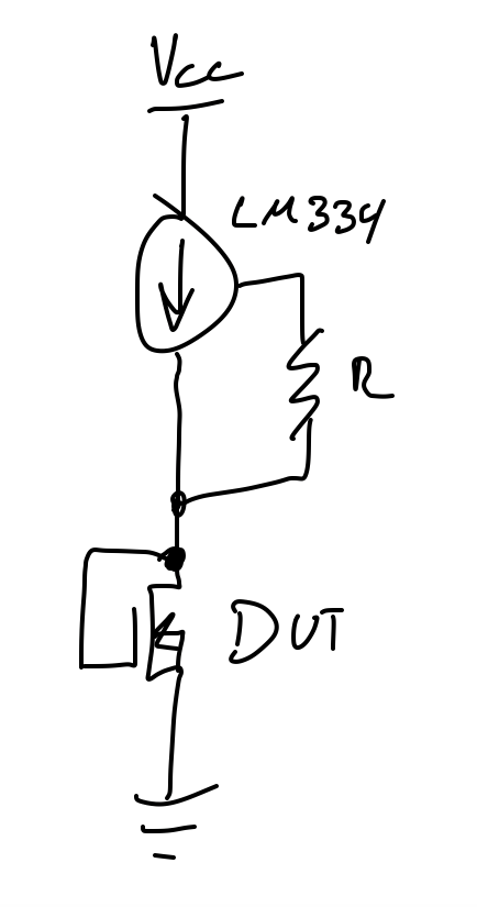
Using MOSFETs as TID sensors is common enough. A term that you can use for more research is RADFET. The best way to measure threshold voltage is to sweep the gate voltage. In my experience however, if you intend to measure this in a non-lab environment (say, in a satellite), I would recommend that you instead connect the gate to the drain, force a small constant current (maybe 10uA) from the drain to source, and measure Vds (which is equal to Vgs in this configuration). This won’t give you the threshold voltage per se, but this will produce a voltage that changes as dose accumulates, is a far easier metric to measure, and is as equally valid as measuring the threshold voltage to determine TID. You can’t really predict the shift in threshold voltage according to TID unless your MOSFETs are all from the same batch (manufacturing defects and tolerances), and you need to calibrate them in order to obtain a calibration curve (this is done by simply going to irradiate several (the more the better, I suggest at least 10 for statistical significance). Alternatively, you can buy pre-calibrated ones from companies who make MOSFETs for this intended purpose like Varadis. If you really want to measure the threshold voltage, you could read MIL-STD-750, which outlines how to measure the threshold voltage.
The wiring is simple enough, see image. Since the gate is connected to the drain, you can measure either Vds or Vgs. They are equal in this configuration so it doesn’t matter.